16.10.2026
Design and operating principle of an axial electric motor
electric motor, schematic, principle
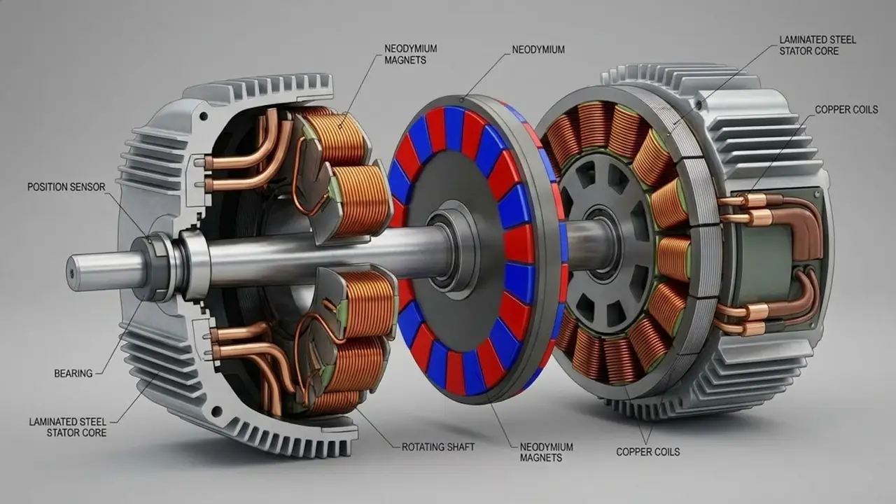
In an axial electric motor featuring a single rotating rotor disk positioned between two stationary stators, the rotor sits at the center of the assembly, flanked on both sides by annular electromagnetic units. The working surfaces of the stators are parallel to the rotor surfaces, and the primary magnetic flux traverses the air gaps along the axis of rotation. Permanent magnets with alternating north and south poles are mounted on both sides of the rotor. When electric current is supplied to the stator windings, magnetic fields are generated that interact with the fields of the permanent magnets. Electromagnetic forces produce torque, causing the rotor to turn relative to the stationary stators. Since both stators operate in conjunction with a single rotor, their electromagnetic torques combine, provided the windings are correctly calculated and the current control is synchronized. In this dual-stator, single-rotor axial motor design, the magnets on opposite sides of the disk are oriented with opposing poles facing outward. Around the circumference of the rotor disk, the magnets alternate in a sequence of N – S – N – S – N – S on each side; a south pole is positioned directly opposite every north pole. This configuration ensures a continuous magnetic flux path. Magnetic flux lines emerge from the windings of one stator, cross the air gap, and enter the north pole of a rotor magnet. The flux then passes through the rotor body—specifically, its internal steel magnetic core—before exiting through the south pole of the magnet on the opposite side of the disk, crossing the second air gap, and entering the windings of the second stator. This creates a unified, efficient magnetic circuit with minimal leakage, thereby delivering the high power density and compact size characteristic of axial motors. This design provides two active rotor working surfaces instead of one. This allows for the utilization of both sides of the magnetic system and potentially increases torque for a given diameter. Furthermore, the symmetrical arrangement of the stators enables the compensation of a significant portion of axial magnetic forces: one stator attracts the rotor in one direction, while the other pulls it in the opposite direction. The axial motor's rotor consists of a rigid disk connected to the motor's output shaft. Its function is to maintain the precise positioning of permanent magnets at high speeds, transmit torque to the gearbox shaft, and withstand cyclic loads. The geometry of the disk and the magnet mounting system are designed to account for centrifugal forces, mechanical stresses, thermal expansion, and vibrations. High-energy permanent magnets based on neodymium, iron, and boron are used as the magnetic material; their specifications are selected based on operating temperature and resistance to demagnetization. The magnets are arranged circumferentially in a calculated pole sequence, with a mounting system ensuring secure fixation at maximum speeds and during repeated acceleration and braking cycles. To reduce motor weight, carbon fiber and other composite materials are employed in areas where they provide sufficient strength; however, carbon fiber is not used as a substitute for magnetically conductive material where a magnetic flux path is required. The rotor's structural design is determined following electromagnetic and structural analyses. For high-speed machines, dynamic balancing, runout checks, and testing of the rotor under design operating conditions are mandatory. A hollow shaft may be used to reduce weight and facilitate the integration of sensors, cables, or auxiliary components. Two stationary, ring-shaped stators are positioned on either side of the rotor. Each stator houses magnetically conductive elements and copper windings. The design features segmented magnetic cores and concentrated windings; these simplify the manufacturing of individual components, reduce the length of conductor end turns, and facilitate cooling. The magnetic core is made of a material suitable for alternating magnetic fields; electrical steel with appropriate characteristics is used for the motor. The winding cross-section and number of turns are determined by the supply voltage, permissible phase current, required torque, and rotational speed range. Air gaps between the rotor and both stators must be maintained under all design-specified operating conditions. This requires a rigid housing, precision-machined mounting surfaces, reliable bearings, and control of thermal deformation. Slight deviations in rotor position can lead to magnetic field non-uniformity, increased vibration, and contact between rotating and stationary parts.